Additional UE Setup parameters are described in PUSCH Common (Advanced LTE-A Pro FDD Uplink), PUCCH Common (Advanced LTE-A Pro FDD Uplink), and Sounding Reference (Advanced LTE-A Pro FDD Uplink).
|
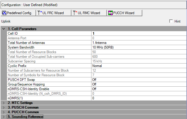
1. Cell Parameters |
|---|
Range: 0 to 503
Default: 0
Enter a value for the cell ID. See 3GPP TS 36.211.
Choice: (It depends on Total Number of Antennas.)
0 (1 Antenna case)
0 | 1 (2 Antenna case)
0 | 1 | 2 | 3 | 4 (4 Antenna case)
Default: 0
Double-click or use the drop-down menu to set the antenna to be used for transmitting the uplink signal.
The available selections are determined by the Total Number of Antennas setting, see this parameter below.
When the MIMO Quick Setup is selected, this parameter is hidden.
See 3GPP TS 36.211 for more information.
Choice: 1 Antenna | 2 Antennas | 4 Antennas
Default: 1 Antenna
Double-click or use the drop-down menu to set the total number of physical antenna port configuration used for uplink transmission in this cell.
When the MIMO Quick Setup is selected, this parameter is read-only.
See 3GPP TS 36.211 for more information.
Choice: 1.4 MHz (6RB) | 3 MHz (15RB) | 5 MHz (25RB) | 10 MHz (50RB) | 15 MHz (75RB) | 20 MHz (100RB)
Default: 10 MHz (50RB)
Use the drop-down menu to set the system bandwidth and number of Resource Blocks (RB).
When the system bandwidth is changed, the software automatically adjusts the value in the Total number of Resource Blocks cell, the Total number of Occupied Sub-carriers cell and so on.
The resource blocks and some parameters are reconfigured by changing the System Bandwidth parameter.
In the case (1) or (2), auto configuration is done for Frequency Offset and Cell ID.
(1) When any action, Add CC, Delete CC, Copy CC, or Change System BW is executed and Auto Carrier Aggregation Configuration is on.
(2) When Auto Carrier Aggregation Configuration is changed to on from off.
Auto configuration sets the Cell ID to the same value as Component Carrier Index.
If Auto Carrier Aggregation Configuration is set to off, auto configuration does not work.
System Bandwidth is automatically set to 10 MHz or 20 MHz when Resource Allocation Type 3 is changed to on.
Resource Allocation Type 3 is automatically set to off when System Bandwidth is changed to a value other than 10 MHz or 20 MHz.
The value in this cell is set by the software based on the System Bandwidth setting.
The value in this cell is set by the software based on the System Bandwidth setting.
Default: 15 kHz
Displays the subcarrier spacing for the uplink. Only the 15 kHz subcarrier is supported in this release.
Choice: Normal | Extended
Default: Normal
Double-click or use the drop-down menu to select a Normal or Extended cyclic prefix. The software sets Number of Symbols for Resource Block based on the cyclic prefix selection.
Cyclic Prefix is automatically set to Normal when Resource Allocation Type 3 is changed to on.
Resource Allocation Type 3 is automatically set to off when Cyclic Prefix is changed to Extended.
See 3GPP TS36.211 5.2.4 for more information.
Default: 12
Displays the number of consecutive subcarriers in an uplink resource block.
Default: 7 for Normal Cyclic Prefix; 6 for Extended Cyclic Prefix
Displays the number of consecutive OFDM symbols in a uplink slot. The software sets the Number of Symbols for Resource Block based on the Cyclic Prefix selection.
Choice: Off | On
Default: On
Double-click or use the drop-down menu to turn PUSCH DFT Swap on or off.
PUSCH DFT Swap influences how data is mapped to resource elements in the physical uplink shared channel after discrete Fourier transform is performed. PUSCH DFT Swap can be turned on or off to provide two different interpretations of how data should be mapped to resource elements in PUSCH channels. For details about this feature, contact your Keysight representative.
Choice: Off | Group Hopping | Sequence Hopping
Default: Off
Set one or both of the following parameters to On to allow manual control of Hopping:
Double-click or use the drop-down menu to select Group Hopping or Sequence Hopping or to turn hopping Off.
There are 17 different hopping patterns. If sequence or group hopping is disabled, sequence index 0 is used. If sequence or group hopping is enabled, the sequence index is given by the physical-layer cell identity.
See 3GPP TS36.211 for more information about Group Hopping and Sequence Hopping.
Choice: On | Off
Default: Off
Double-click or use the drop-down menu to turn the flag which is whether nDMRS-CSH-Identity is enable or not. See 3GPP TS36.211 5.5.2.1.1 for more information.
Range: 0 to 509 Default: 0 Enter a value of nDMRS-CSH-Identity (N_csh_DMRS_ID). This parameter is active only when nDMRS-CSH-Identity Enable is on.
See 3GPP TS36.211 5.5.2.1.1 for more information.
Range: 0 to 509
Default: 0
Enter a value of nDMRS-CSH-Identity (N_csh_DMRS_ID). This parameter is active only when nDMRS-CSH-Identity Enable is on.
See 3GPP TS36.211 5.5.2.1.1 for more information.
Choice: 0 | 2 | 3 | 4 | 6 | 8 | 9 | 10
Default: 0
Double-click or use the drop-down menu to select nDMRS(1) value which is given by 36.211 Table 5.5.2.1.1-2. This value is used for both PUSCH and PUCCH.
See 3GPP TS36.211 5.5.2.1.1, and 5.5.2.2.1 for more information.